YASim Fuselage Elements
By Gary "Buckaroo" Neely
Fuselage elements define structures that have mass and aerodynamic influence but otherwise don't determine primary flight characteristics. They serve as ground contact points, act as simple surfaces that contribute drag, and affect mass distribution.
A typical fuselage element looks like this:
<fuselage ax="0" ay="0" az="0" bx="-5.569" by="0" bz="0.255" width="1.200" taper="0.3" midpoint="0.5" />
Most aircraft will have at least one fuselage element representing the actual aircraft fuselage. Additional Fuselage elements can be used to represent engine nacelles, or wheel pants, external fuel tanks, static weapon structures, etc. You can have as many fuselage structures as you need, or none at all.
Fuselage Attributes
The structure of a fuselage element should always contain the following attributes:
<fuselage ax="..." ay="..." az="..." bx="..." by="..." bz="..." width="..." />
A fuselage element also has these optional attributes:
midpoint (defaults to 0.5)
taper (defaults to 1)
cx, cy, cz (each defaults to 1)
idrag (defaults to 1)
In most cases you will provide values for midpoint and taper rather than use the defaults. The attributes ax, ay, az are the coordinates for the center of the forward end of the structure, and bx, by, bz determine the center of the aft end. Width is the width of the structure at its midpoint.
midpoint and taper
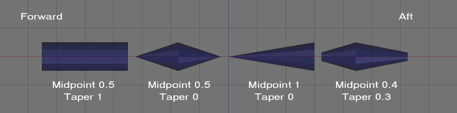
The defaults create a cylindrical structure, but changing the defaults can create anything from a cone to a truncated biconic structure. Midpoint defines the fractional distance of the widest point of the structure from the front to the aft end. So 0.5 is a true midpoint, 0.25 has the widest part 1/4 the distance from the forward end. Taper determines how much the structure deviates from a cylinder. A taper of 1 creates a cylindrical structure, a taper of 0 creates what is in essence two cones glued together at their bases. Any taper value between 0 and 1 creates two truncated cones glued together at their bases, with the structure becoming more cylindrical as taper is set closer to 1.
The following image illustrates the use of midpoint and taper to control the shape of the fuselage element:
cx, cy, cz
The attributes cx, cy, cz are scalars that multiply the drag forces acting on the structure. Fuselage elements are symmetrical about the x axis, but you can use these attributes to make them appear less symmetrical for drag calculations. Note that these are scalars to forces, not to physical dimensions, so they have no effect on mass distribution.
Let's say you are modeling a fuselage like that of a Piper Cub that has a cross-section approximately twice as tall as it is wide. In this case, you might set cy=2 and cx=2. To see why, consider a wind blowing sideways against the fuselage (from the y direction). Because the fuselage is twice as tall as it is wide, it has double the surface area when viewed from the side as compared to the top. Therefore the wind has double the force when acting on the side (cy=2). If wind is blowing from the front (the x direction) it would also see double the surface for the same reason, so the force is doubled (cx=2). If blowing from the top (z direction) it would see no change in force because we're using the standard dimensions given by the length and width of the fuselage, unmodified by cz (cz=1, the default).
As a second example, say your fuselage is short and wide like that of a Velocity, with a height about 2/3 the width, you could set cy=0.67 and cx=0.67, providing less sideways and frontal surface area than the fuselage attributes would normally give.
idrag
I haven't used the fuselage idrag attribute and don't trust it. Since fuselage elements are internally divided into segments with each segment treated as a simplified surface, then fuselage idrag likely suffers from the bug that reverses the effects. If so, then decreasing idrag from 1 actually increases induced drag. To decrease idrag, try setting idrag > 1. I haven't tested this for fuselage idrag attributes, so I if you use idrag for fuselage elements, I suggest you perform flight tests to be certain you are getting the results you expect. See Induced Drag and YASim.
Contact Points
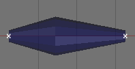
The foreward and aft coordinates of each fuselage element are contact points for ground interaction. Ground contact with the object itself will do nothing, only the end points trigger a contact. The small white x's at right show the location of contact points for a typical fuselage element.
Mass and Drag Distribution
Internally, YASim sees each fuselage element as a number of sub-elements. Each fuselage object is divided into a number of segments equal to the ratio of object length to width. So a fuselage that is five times longer than it is wide would be distributed as 5 segments. Each segment is weighted and scaled acording its location in the object and the object's taper and midpoint. Each segment is added to the mass distribution of the aircraft. Drag effects are calculated separately for each segment. Segments are independent-- there is no slipstream or drafting benefit. Unless I've misinterpreted the code, since the relative wind passes through each segment in turn, this suggests YASim may actually be generating excessive drag along the x axis. By tapering the object this effect is considerably reduced because drag of any given segment is based on the segment's 'footprint', but the algorithm still seems less than optiimal to me.
Combining Fuselage Objects
You can usually use a single fuselage element to simulate most objects. If I can, I try to make a fuselage or nacelle using a single fuselage element, using the philosophy of Keep-It-Simple-Stupid. But you can also combine three or more fuselage elements to form a shape that more closely resembles a true fuselage as shown here:
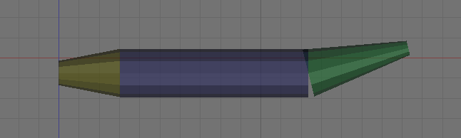
Looking at the YASim code, this seems to have benefits and penalties. Combining objects can give a better mass distribution, though you could do the same with ballast elements. Combinining objects yields approximately the same number of segments as a single object having the same length and width. As noted above, there is no drafting benefits from combinations since all segments are considered separately. Combining objects creates additional unnecessary contact points, since the only points that matter are the ones at either extreme of the combined object.
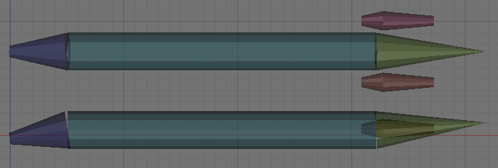
Here is an example fuselage layout based on my MD-81 model. This layout features three bodies making up the fuselage, and two engine nacelles, shown as a top and side view in the illustration.
<fuselage ax="0" ay="0" az="-0.26" bx="-5.09" by="0" bz="0.51" width="3.33" taper="0.3" midpoint="1" />
<fuselage ax="-5.09" ay="0" az="0.51" bx="-32.16" by="0" bz="0.51" width="3.33" taper="1" midpoint="0.5" />
<fuselage ax="-32.16" ay="0" az="0.51" bx="-41.89" by="0" bz="1.16" width="3.33" taper="0" midpoint="0" />
<fuselage ax="-30.85" ay="2.7" az="0.62" bx="-37.25" by="2.7" bz="0.62" width="1.7" taper="0.5" midpoint="0.3" cx="0.1" />
<fuselage ax="-30.85" ay="-2.7" az="0.62" bx="-37.25" by="-2.7" bz="0.62" width="1.7" taper="0.5" midpoint="0.3" cx="0.1" />
Other Thoughts
When creating fuselage bodies for structures like engine nacelles, keep in mind that these structures usually pass air through them, either as an enclosure for a jet engine, or to direct airflow past engine blocks in the case of piston engines. They usually have very little mass and their drag effects are much less than a similar body that does not pass air through it. Consider scaling down the properties of such fuselage objects to reduce their effects. One way to mitigate the airflow problem is to reduce the drag effects along the object's x axis using the cx attribute, for example, cx=0.2.