YASim Landing Gear and Surface Interaction
By Gary "Buckaroo" Neely
The <gear> element is the primary contact point for ground or water surfaces and the only contact points which can be disabled (retracted). Most aircraft will define three landing gear elements similar to the following example:
<gear x="-0.796" y="0" z="-1.070"
	dfric="0.5"
	sfric="0.6"
	spring="0.9"
	damp="0.8"
	compression="0.08"
        castering="1">
  <control-input axis="/controls/gear/nosewheel-lock" control="CASTERING" src0="0" src1="1" dst0="1" dst1="0" />
  <control-input axis="/controls/gear/gear-down" control="EXTEND"/>
  <control-output control="EXTEND" prop="/gear/gear[0]/position-norm"/>
  <control-speed control="EXTEND" transition-time="12"/>
</gear>

<gear x="-3.750" y="0.967" z="-1.015"
	dfric="0.5"
	sfric="0.6"
	spring="0.8"
	damp="0.8"
	compression="0.22">
  <control-input axis="/controls/gear/brake-left" control="BRAKE"/>
  <control-input axis="/controls/gear/brake-parking" control="BRAKE" split="true"/>
  <control-input axis="/controls/gear/gear-down" control="EXTEND"/>
  <control-output control="EXTEND" prop="/gear/gear[1]/position-norm"/>
  <control-speed control="EXTEND" transition-time="12"/>
</gear>

<gear x="-3.750" y="-0.967" z="-1.015"
	dfric="0.5"
	sfric="0.6"
	spring="0.8"
	damp="0.8"
	compression="0.22">
  <control-input axis="/controls/gear/brake-right" control="BRAKE"/>
  <control-input axis="/controls/gear/brake-parking" control="BRAKE" split="true"/>
  <control-input axis="/controls/gear/gear-down" control="EXTEND"/>
  <control-output control="EXTEND" prop="/gear/gear[2]/position-norm"/>
  <control-speed control="EXTEND" transition-time="12"/>
</gear>
This is a tricycle arrangement with gear elements for the nose wheel, left main, and right main. Let's look at how to use the gear element in a YASim aircraft.
Gear Element Basics
Each gear element consists of a contact point, a number of optional attributes, and a number of optional controls and outputs. A retractable gear element will generally be defined as follows:
<gear x="-0.796" y="0" z="-1.070"
        ...optional attributes...
        >
  <control-input ... />
  <control-output ... />
  <control-speed ... />
</gear>
A non-retractable element is even simpler:
<gear x="-0.796" y="0" z="-1.070"
        ...optional attributes...
        >
  <control-input ... />
</gear>
A gear element should always have an x, y and z attribute which defines the contact point. Note that there are two other potential contact types other than gear which I'll discuss shortly. Many gear elements will also have control subelements for assigning functions like braking. Those with retractable gear will have a control for extending the gear, a control output for showing the position of the retractable gear, and a control-speed to regulate the time required to extend or retract the gear.
You can declare your gear in any order, but order determines the sequence of properties in the property tree. For example, in the above tricycle example, the nose gear is gear "0", the left main is "1", and the right "2". You may have as many gear elements as you need. Some tricycle arrangements also feature a tail skid, while some gliders have small wheels attached to the wing tips. These can all be configured using <gear> elements.
Gear Element Attributes
Landing gear have quite a few interesting attributes:
x, y, z
compression
upx, upy, upz
spring
damp
initial-load
sfric
dfric
castering
skid
on-solid
on-water
ignored-by-solver
spring-factor-not-planing
speed-planing
reduce-friction-by-extension
If this looks complicated, then fear not, because most are optional and many are for special applications. We'll look at each one in detail.
The Surface Contact: x, y, z
The x, y, and z attributes define the gear's surface contact location relative to the aircraft's reference datum. YASim calls this "the location of the fully-extended gear tip". Translation: this is the contact point of the gear with the hypothetical ground when the gear has no compression, in other words, as if the gear is supporting no weight. This is not the location of the contact point when the aircraft is sitting on the ground, as that location assumes weight on the gear and some degree of compression. Since YASim calculates compression at all times that the landing gear is deployed, it needs to know the fully-extended contact point as a base reference. You should always provide values for these three attributes.
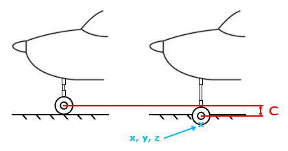
The illustration shows a ground contact point for a typical tricycle nose gear. Note that the gear is fully extended. "C" refers to the compression length, which I'll discuss next.
When considering tires, I often assume some tire deformation when contacting the ground, something like 5-10% of the tire radius. In other words, my contact point won't be the outermost circumference of the tire, but a point slightly inside the tire. This will look more natural when the aircraft is sitting on the tarmac, particularly for heavier aircraft.
Gear aren't the only elements that can interact with a ground or water surface. There are two other possible types of contact points:
fuselage elements
flight surface tips
Ground contact with a fuselage contact point will result in a crashed condition. This is what triggers a "crash" if you land gear-up in a retractable gear aircraft. The midpoint of the tip chord of a flight surface also serves as a contact point but will not trigger a crashed condition.
Compression
The compression attribute sets the maximum distance in meters that the gear will compress under load.
compression (default 1)
Be sure to define this value since the default of 1 meter is much too large for general aviation aircraft. The above image shows how the compression length (shown as "C") is determined. Different gear mechanics will have different means of absorbing shock. All YASim cares about is how the load translates the point of contact with the ground (or water in the case of floats).
The compression attribute has a potentially significant effect on drag. See Gear Drag Effects below.
When gear is under load, YASim defaults to a compression orientation that is straight up along the z axis. You can define three optional attributes to change this behavior:
upx, upy, upz (default 0, 0, 1)
These values change the strut compression orientation. The default values of 0, 0, 1 indicate a compression that is vertical. For most configurations the default will work fine, especially if the angle of compression varies only slightly from the vertical. Where this is not the case, the direction of compression can be expressed as a vector.
Let's look at an example of compression orientation. A tricycle landing gear configuration is shown below in order of nose, left main, and right main. In the first case, they all use the default values of upx="0" upy="0" upz="1".
<gear x="2.5" y="0" z="-1.5"
  compression="0.5"
  ...
</gear>

<gear x="-0.15" y="1.2" z="-1.5"
  compression="0.5"
  ...
</gear>

<gear x="-0.15" y="-1.2" z="-1.5"
  compression="0.5"
  ...
</gear>
The illustration shows the gear compression orientation as vertical. All compressions are straight upwards.
The same set of gear again, with changes to strut compression orientation:
<gear x="2.5" y="0" z="-1.5"
  compression="0.5"
  upx="-0.2" upy="0" upz="1"
  ...
</gear>

<gear x="-0.15" y="1.2" z="-1.5"
  compression="0.5"
  upx="0" upy="-0.2" upz="1"
  ...
</gear>

<gear x="-0.15" y="-1.2" z="-1.5"
  compression="0.5"
  upx="0" upy="0.2" upz="1"
  ...
</gear>
 |
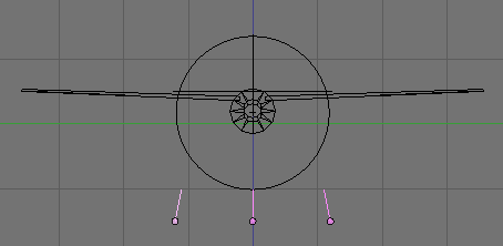 |
The gear compression orientation has changed. The nose gear now compresses with a slightly aft angle, and the main gear now have a negative camber (the compression is aimed inward toward the fuselage).
If you use a configuration other than the default, be careful to define all three components of the vector, even if the value is 0. Otherwise YASim will either use the defaults or might generate an error.
Spring Behavior
Gear compression is governed by a physical spring simulation. YASim initially configures this for you, giving you two multipliers to alter the default behavior:
spring (default 1)
damp (default 1)
Internally YASim generates a spring constant such that at full compression the gear will support 10 times the mass of the aircraft. The "spring" attribute is an optional multiplier for this constant. Setting the spring value to greater than 1 will allow the gear to support a greater mass at full compression, making the gear more stiff, in other words, less compression for the same weight. Setting the value less than 1 will decrease the stiffness of the gear, allowing more compression at the same weight.
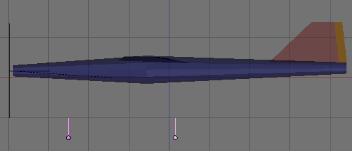
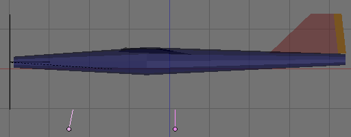
Below left is an Edgley Optica with main gear spring attributes set to 1. Below right is the Optica with the spring attributes set to 0.6.
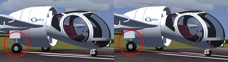
Notice that with the smaller spring values, the Optica sits lower on the main gear. The struts are considerably more compressed.
Compression length appears to be a target value rather than a hard limit. It is possible to exceed the compression length if enough force is applied to the gear, such as a hard landing or even the simple weight of the aircraft at rest. The spring attribute has a significant effect this. With the Optica, a spring setting of 0.5 will result in the aircraft sagging to the ground-- the non-gear contact points will then intersect the ground, resulting in a "crashed" condition. Some real-world compression simulations will be hard to achieve. For example, the MD-80 series has a very short nose gear compression. Getting a good compression reaction in YASim for such a large aircraft is difficult without exceeding the compression length, even with fairly mild nose gear touch-downs. Unfortunately there is currently no way to set a hard stop on gear compression, though actually hitting the stop would probably damage most real aircraft.
The spring damping coefficient is another automatically generated internal value. The damp attribute is an optional scalar for that value. A perfect, frictionless spring system will continually oscillate back and forth with the same amplitude if nothing is acting to resist the movement. The damping effect provides this resistance.
The damping effect is easily observed by selecting a general aviation Flightgear model with a tricyle gear arrangement. Allow the aircraft to begin moving on the tarmac and then brake quickly. Observe the effects using an external view. With damping set to the default of 1, the nose of the aircraft plunges down and then recovers, with little or no oscillation. Change the nose gear damping to a very small value like 0.1 and repeat the test. This time the nose plunges down and recovers but then repeats the behavior with decreasing amplitudes until the oscillation stops entirely.
For most aircraft the default damp value will usually work fine, particularly with heavier models. Lighter aircraft might have more "bounce" in some gear effects, so reducing the damp value from 1 may be appropriate. If you have personal experience or can observe a video of the aircraft, you might have some insight and can adjust damping accordingly. Rarely will you have to increase damp much beyond 1, and the YASim document warns that high values may make the algorithm unstable. I've never experienced problems with too much "bounce" in a gear except with jitter issues, which I believe to be a different problem.
A third seldom-used spring-related attribute is available to alter spring behavior:
initial-load (default 0)
This value can give a spring an initial load, allowing the use of a lower spring multiplier. It may help to think of tires as absorbing some of the shock that would otherwise be absorbed by the gear. The value is supposed to be expressed in multiples of the compression. Presumably this means that if your compression length is 0.2, then initial-load could be set to 0.2, 0.4, 0.6, etc.
I don't fully understand this attribute and have not used it. I believe some developers have used it to help reduce gear jitter issues. Small values can sometimes introduce jitter, and large values can make the gear too "mushy", such that the aircraft may sink through the ground if too much force is applied, even simple braking. I've not given the attribute much study.
The initial-load attribute was added by Maik Justus.
Static and Dynamic Friction
Static and dynamic friction coefficients influence the gear's resistance to movement when on a surface. YASim generates static and dynamic value based on the current simgear terrain material friction values, but you have two gear attributes which allow you to modify the generated values:
sfric (default 0.8)
dfric (default 0.7)
The static coefficient influences the force necessary to overcome the initial resistance to movement. The dynamic (or kinetic) coefficient influences the force necessary to keep the gear moving once in motion. A larger friction value decreases the stopping distance of the vehicle. The static value should be larger than the dynamic value. The static friction resistance force will rise with the applied force until it reaches a threshold, where the friction force falls off quickly to the dynamic range and remains relatively constant regardless of the applied force.
The defaults work reasonably well for configurations using wheels on concrete or asphalt, though I often play with values ranging from 0.6 to 0.8. Dynamic friction will be only slightly less than static for wheels. For skids, the values will likely have a greater separation-- try changing the default dfric to 0.45.
The Castering Wheel
Most wheel gears are fixed, free-rolling forward or backwards but resisting sideways skidding. A castering gear allows relatively free skidding movement left or right once static friction has been overcome. Many tail-draggers feature free-castering tail wheels. Internally, the ground velocity of a gear consists of a rolling and a skidding component. Setting castering to 1 greatly magnifies the influence of the skidding component.
castering (default 0)
Castering should normally be off (the default) for main gear and for steerable nose or tail wheels. Learn more about controlling castering in the Control Input section.
As a side note, I think YASim would benefit from allowing the developer to place an optional scalar on the skidding component of castering so that the developer has some control over the effect in addition to the friction values.
Skids
Not all landing gear are wheels. Many helicopters employ simple skids for gear. You can declare a gear to be a skid by setting the following attribute to 1:
skid (default 0)
Internally "skid" is assigned to a variable called "brake". This appears to be a multiplier to the rolling and skidding friction values of the base ground material and applied to the steered (vs. skidding) component of gear interaction with a surface. The default value of 0 grants the base ground friction factor no influence for steering, while ground rolling friction gets maximum influence. A value of 1 grants maximum influence to ground friction factor, and no influence for ground rolling friction. The base factors are derived from the simgear scene material.
Limiting Applicable Surfaces for a Gear
Gear can interact with ground surfaces, water, or both. The following two attributes determine the surface where the gear is applicable:
on-solid (default 1)
on-water (default 0)
For example, if a gear is set for use only on a solid surface then it will have no effect on water. The gear will be ignored and the aircraft will likely contact the water with some other contact point, either another gear element, a fuselage segment, or a wingtip.
If using conventional ground landing gear, there is no need to include these attributes as the defaults will work well. When using a gear element as a float or flying boat contact point, you should provide these attributes using the following values:
on-solid="0"
on-water="1"
Other applications are skid-floats for helicopters, where you might have a contact point that is valid on water and on land.
The "Ignored-By-Solver" Attribute
YASim normally uses all defined gear elements for calculating the spring constants which determine the base physical modeling of spring behavior for each gear. This is fine for aircraft having only the usual set of three ground-based landing gear. But some gear definitions are best left out of the calculations for spring constants. YASim has a special attribute for doing just that:
ignored-by-solver (default 0)
This attribute tells YASim to ignore a gear when calculating spring constant weightings. If an aircraft does not have water-based gear, then you can usually use the default or simply not include this attribute. If an aircraft has both terrestrial landing gear and water-based gear, then include ignored-by-solver="1" for each water-based gear element. If you do not, YASim will include the water-based gear elements when determing the spring constants for the terrestrial gear.
Consider using ignored-by-solver for any gear that is not used for significant distribution of the aircraft's weight when at rest under normal circumstances. This might include situations like small wheels at the wingtips of some sail planes.
Important: do not set all gear elements to be ignored-by-solver. The command-line YASim solver may not gripe at you, but Flightgear will spew nasty errors that may not be easily traced to this setting.
YASim features a serviceable simulation of interaction with a water surface that can be used for flying boats and seaplanes. To use a gear element for this purpose, be sure to set these attributes:
on-solid="0"
on-water="1"
ignored-by-solver="1"
Using gear as contact points to simulate flying boat hulls or seaplane floats requires different thinking than land-based gear. It helps to know something about takeoffs using boat hulls or floats. There are numerous good online pilot references that discuss the procedures, but here is a very brief summary of the basics.
For floats on water, the problem of friction is more complex than ground-based operations. Floating drag is governed by frictional resistance, wave-making resistance, the shape of the hull, and other factors. This resistance or drag varies with the square of the speed of the object through the water. Resistance also depends on whether the object is ploughing though the water or hydroplaning on the surface, also known as being "on the step". For a flying boat or a seaplane it's important to start planing as soon as possible, otherwise the drag of plowing through the water will skyrocket with the increase in speed.
For many real-world seaplanes, water drag peaks around 27 knots. At that point the aircraft begins planing and water drag begins to fall off. This depends greatly on the aicraft design, the loading of the aircraft, the condition of the hull, and the surface conditions of the water. Depending on these conditions and altitude, the aircraft might not be able to get airborne.
Back to YASim. There are three additional attributes applicable to water-based gear. When used wisely and with lots of testing and tweaking, these attributes can give a reasonable simulation of flying boats or seaplane takeoffs.
spring-factor-not-planing (default 1)
speed-planing (default 0)
reduce-friction-by-extension (default 0)
The first two attributes, spring-factor-not-planing and speed-planing, influence the spring constant of a float in water. The spring-factor-not-planing attribute is a multiplier to the spring coefficient when below planing speed, defined by speed-planing. The aircraft will sit lower in the water when not planing. When planing, the water begins acting "harder" and the vehicle will sit higher on the surface. Anyone who has tried water skiing has likely noticed this effect, which is particularly annoying when one loses control and smacks into the water. Trust me on this one.
Experiment for best results with your flying boat or seaplane. Keep in mind that planing usually begins somewhere around 27-30 knots, and the spring effects below planing are likely to be softer than when hydroplaning, so your spring-factor-not-planing attribute will likely be some fractional value rather than a number greater than 1.
The third attribute, reduce-friction-by-extension, can reduce friction based on gear compression. Using the default of 0, friction does not vary with compression. Using a value of 1, friction is linearly reduced as compression varies from fully compressed to no compression. With no compression on the gear, friction is then 0. Using a value of 0.5, friction varies with compression from full at max compression to half at no compression.
This is a key value for simulating the transition from ploughing through the water to hydroplaning. As the aircraft moves faster, more lift is generated, taking some load off the gear and reducing compression. When using reduce-friction-by-extension, this begins to reduce the friction imposed by the water surface. This is important when considering the squared velocity effects of water drag. The actual value used must be found by experimentation while knowing the water takeoff characteristics of your aircraft.
The reduce-friction-by-extension attribute is especially useful when used with the speed-planing/spring-factor-not-planing attributes, since a stiffer spring means less compression and therefore less friction when using reduce-friction-by-extension.
If the reduce-friction-by-extension value is greater than 1, the point of zero friction is achieved before the gear is fully extended. The algorithm doesn't clamp the friction to 0 at extensions beyond this point-- in other words, the friction multiplier can become a negative value. Since this is meant to be used with floats, this is likely intentional. In practice, I've found it to be sometimes necessary to use a value greater than 1, otherwise the aircraft may not get over the water-drag hump and start planing.
Gear used as floats have some special concerns regarding drag and YASim solutions. Be sure to read the sections below concerning landing gear and drag.
  <control-input axis="/controls/flight/rudder" control="STEER"/>
  <control-input axis="/controls/flight/rudder" control="STEER" square="true"/>
Control inputs have some interesting optional attributes:
invert
src0/src1/dst0/dst1
square
For aircraft having a steerable tail wheel, the "invert" attribute is useful to correct for the rudder control input, which is itself normally inverted due to how vertical flight surfaces are configured.
<control-input axis="/controls/flight/rudder" control="STEER" invert="true"/>
You will not need to do this for a nose wheel.
The optional attributes "src0", "src1", "dst0" and "dst1" allow you to alter the range of control inputs. Here's an example:
<control-input axis="/controls/flight/rudder" control="STEER" src0="-1" src1="1" dst0="-0.5" dst1="0.5"/>
In this case, we're taking the possible input range of -1 to 1 and interpolating it to export an output range of -0.5 to 0.5. In other words, if the rudder control value is 1, the gear steering control will receive 0.5. These attributes can be used as an alternate method of inverting a control:
<control-input axis="/controls/flight/rudder" control="STEER" src0="-1" src1="1" dst0="1" dst1="-1"/>
The "square" attribute provides a method of giving more precise control in the small ranges of steering by squaring the value of the control input.
<control-input axis="/controls/flight/rudder" control="STEER" square="true"/>
In this example, a rudder control input of 1 creates an geer steering control input of 1, but a rudder input of 0.1 gives a steering input of 0.01. This can be useful for aircraft with longer or faster takeoff runs where too much authority on the nose wheel can cause the plane to track wild.
Applying Brakes
The previous examples have mapped the rudder control to a gear, but of course it's also useful to map braking controls to gears. This is used for differential braking and implementing the parking brake.
  <control-input axis="/controls/gear/brake-left" control="BRAKE"/>
  <control-input axis="/controls/gear/brake-parking" control="BRAKE"/>
This example shows the left-brake and parking break controls being mapped to a gear's braking function. So if either control is applied, the gear's brake function will be activated. Normally you would want to do this for the left main and right main gear (substituting "brake-right" for the right main gear).
Gear Extension
<control-input axis="/controls/gear/gear-down" control="EXTEND"/>
This subelement maps a controlling property to the extended condition of the gear. A value of 0 indicates the gear is retracted, 1 indicates fully deployed.
A gear element's contact point is active only when it is in the fully extended position. In other words, the associated property must have a value of 1. Any value less than 1 will disable the contact points. If the aircraft is sitting on the ground and you initiate a gear retraction, the gear contact points are lost and the aircraft will fall to the ground. The fuselage contact points will intersect with the terrain and a "crashed" state will be set.
Locking the Tail Wheel
Many tail-draggers have a tail wheel that is either free-castering or can be locked into a straight, in-line position for takeoff and landing. YASim provies a control subelement to toggle the castering feature of gear elements.
<control-input axis="/controls/gear/tailwheel-lock" control="CASTERING"/>
Castering is enabled if this property is true or 1. Since a property like "tailwheel-lock" is usually understood to be locked (non-castering) if set to 1, you might wish to invert the control using either of the following methods:
  <control-input axis="/controls/gear/tailwheel-lock" control="CASTERING" src0="0" src1="1" dst0="1" dst1="0"/>
  <control-input axis="/controls/gear/tailwheel-lock" control="CASTERING" invert="1"/>
Control Output Subelements
Control outputs are the reverse of inputs. They allow you to export YASim's internal control position values as Flightgear properties.
<control-output control="EXTEND" prop="/gear/gear[0]/position-norm"/>
Here we're exporting YASim's value for the current position of a gear extension to the property "/gear/gear[0]/position-norm", where "norm" refers to normalized to the common range of 0 to 1.
Assigning an output property to a control allows you to export what would otherwise be an internal FDM value. In this case, we can export the value of a gear position for use with gear animations. The gear's control input would not work well for this, since it will likely be set to 0 or 1 (up or down), and won't account for the interpolation of the gear from one position to the other. Exporting the actual interpolated position allows the developer to not only animate the gear realistically, but also set up proper cockpit displays to indicate whether the gear is up, in transition, or down and locked.
The Control-Speed Element
Retractable landing gear require time to deploy or retract. You can control this time by using the control-speed sub element.
<control-speed control="EXTEND" transition-time="7"/>
Here we've assigned a 7 second interval for the landing gear to move from from the fully retracted position to the fully extended position. The value of the property associated with the EXTEND control will be interpolated between 0 and 1 over the transistion time in seconds. The default for transition-time is 0, so it's best to provide a value for this subelement.
The YASim document tells us that this sub-element is semi-deprecated by script-based solutions, but for most applications this function is good enough. It uses less resources and is much easier to implement than script-based solutions. It should be your first choice. But it is a simple, linear transistion. If you have a more complex situation, don't hesitate to pre-process control inputs using Nasal scripting rather than use the control-speed sub-element.
Issues Related to Landing Gear and YASim
YASim's implementation of landing gear drag is, for lack of a better word, lousy. It's also bizarre, in at least one respect and without knowing the design logic.
For each gear element, YASim creates a simple "surface" to generate drag effects, using much the same constructs as flight surfaces. The drag factor of the "surface" is based on compression:
gear drag factor = (compression * 3)^2
Compression lengths of a small fraction of a meter yield little or no drag. These situations are typical of an airborne aircraft with gear deployed. But if the compression length gets relatively large, drag can skyrocket and have a major effect on the YASim solution. Be wary of this if your gear elements have long compression lengths or you are using floats.
When implementing floats or boat hulls, some developers use fairly long compression lengths to help simulate a large body floating in water. When the gear is fully extended, as it will be when the gear is unloaded (i.e., when flying), drag is at maximum. With a long compression length this can greatly impact solutions and flight results, far beyond what may be intended.
The consequences of this are not serious for small seaplanes or flying boats where compression values are likely to be a fraction of a meter. But for large aircraft the developer might create large compression lengths approaching a meter or more to allow the hull or float to sit deeper in the water when not planing. Unfortunately this creates huge drag values for the solver and can severely alter an otherwise good solution. Currently the only way I know to deal with this is to keep the compression lengths relatively short and play with other gear attributes.
It's unclear why compression was chosen as a basis for a drag factor. Probably this was a hack solution to supply gear drag. It would have been wiser to allow the FDM developer to set a multiplier for gear drag and a location, since the center of gear drag effects will not be the ground contact point. Addressing the gear drag problem is high on my list if I ever get around to learning how to compile Flightgear.
There are several ways to add gear drag effects, and none of them are particularly great. Some developers create artificial flight surfaces to represent the landing gear struts, pants and wheels. This can work, especially for fixed gear. For retractable gear it generates additional flight surfaces which will always be in existance requiring extra calculations even when not deployed, a generally undesirable thing. Another method is to employ the "weight" element to represent landing gear drag. This element can simulate droppable external stores and features a "size" attribute that generates drag. To be honest, I've never used either method. I understand the cries of how significant gear drag can be, but most YASim aircraft have so many other FDM issues and implausibilities that gear drag is fairly far down the list of concerns.
YASim is notorious for situations where an aircraft sitting on the ground slowly moves or slides over the tarmac, usually with the prevaling wind. If the aircraft has wheels, the wheels can often be observed to be "jittering"-- the wheels spinning backward and forward in quick, slight motions. This effect is sometimes more pronounced in tricycle gear configurations or helicopters using skids. The motion can be numerically observed by opening a property window and inspecting the values for the gear, especially the compression and rollspeed properties.
I don't know what causes this and haven't researched it, though it is a significant YASim annoyance with some aircraft. The effect is rooted in the relationship between the ground surface and the YASim ground contact algorithms and seems to be some sort of insufficiently damped feedback between ground and gear contact, possibly causing a small, undamped micro-bouncing. The effect is often more pronounced on tricycle gear aircraft where the CG is fairly close to the main gear. The problem is influenced by aircraft weight, as it is more commonly seen with lighter aircraft than large planes like airliners.
I don't have a cure-all solution. Sometimes moving the CG or adjusting mass balance can mitigate ground contact jittering. Sometimes changing the gear friction values can reduce jittering. Sometimes adjusting spring values can help the issue. The problem with these solutions is such changes may move these attributes away from desired ranges, compromising the flight model.