YASim Flight Surfaces
By Gary "Buckaroo" Neely
Flight surfaces are the main lifting and control surfaces of an aircraft. The wing and stabilizers are the most common examples. Defining your aircraft's flight surfaces is likely to be your first step in creating a YASim aircraft FDM. Here is a flight surface configuration for a wing featuring flaps, ailerons, slats and spoilers:
<wing x="-22.25" y="1.630" z="-0.648"
      length="15.632"
      chord="6.308"
      taper="0.17"
      sweep="19"
      dihedral="3"
      incidence="1.5"
      camber="0.1"
      twist="-2.0">
  <stall aoa="14" width="8" peak="1.5"/>
  <flap0 start="0" end="0.597" lift="1.5" drag="2.5"/>
  <flap1 start="0.597" end="0.824" lift="1.25" drag="1.2"/>
  <slat start="0" end="1" aoa="3" drag="1.1"/>
  <spoiler start="0.078" end="0.554" lift="0.7" drag="2.0"/>
  <control-input control="FLAP0" axis="/controls/flight/flaps"/>
  <control-input control="FLAP1" axis="/controls/flight/aileron" split="true"/>
  <control-input control="SLAT" axis="/controls/flight/slats"/>
  <control-input control="SPOILER" axis="/controls/flight/spoilers"/>
  <control-output control="FLAP0" prop="/surface-positions/flap-pos-norm"/>
  <control-output control="FLAP1" side="left" prop="/surface-positions/left-aileron-pos-norm"/>
  <control-output control="FLAP1" side="right" prop="/surface-positions/right-aileron-pos-norm"/>
  <control-output control="SLAT" prop="/surface-positions/slat-pos-norm"/>
  <control-output control="SPOILER" prop="/surface-positions/spoiler-pos-norm"/>
  <control-speed control="FLAP0" transition-time="10"/>
  <control-speed control="SLAT" transition-time="10"/>
  <control-speed control="SPOILER" transition-time="1"/>
</wing>
Fortunately most flight surfaces aren't quite so busy.
Flight Surface Basics
A surface is any wing-like component of the aircraft that is primarily concerned with aerodynamic properties. The wing, stabilizer, and vertical stabilizer are all flight surfaces. For many aircraft those will be the only flight surfaces you need be concerned with. But things are often more complex. Sometimes the geometry of a wing is more complicated than a simple Hershey-bar configuration, and can't be expressed easily as a single surface. YASim gives us the flexibility of defining a variety of flight surfaces that in combinantion will determine how the aircraft interacts with the air around it.
Types Of Surfaces
YASim flight surfaces come in four flavors:
wing (required)
hstab (required)
vstab
mstab
They share the same possible attributes and sub-elements and differ only in usage. Let's look at each one.
wing
A YASim FDM must have one and only one <wing> element. This is the primary flight surface. You're not limited to this surface, you can still simulate biplanes, but your FDM must have a single <wing> element. The wing is a mirrored surface. In other words, you define only half of it (the left half), and YASim automatically defines the right half. The wing must have a <stall> sub-element to determine stall behavior, and will likely have one or more control surface sub-elements to represent ailerons, elevator, flaps, slats, spoilers. Each control surface will have at least one control input and a control output. More on these later.
hstab
A horizontal stabilizer. You must have one and only one <hstab> element. This and the <wing> are the only required flight surfaces. The hstab differs from the wing only in that the YASim needs to know which surface it will use to trim the aircraft. It does this by setting the incidence of the hstab flight surface. YASim tries to find a setting that will offset the aircraft's pitching moment at cruise using the aircraft's given parameters and a neutral elevator setting. For this reason, you do not define the incidence of an hstab. Like a <wing>, the <hstab> is a mirrored surface.
There is no reason that the hstab must be positioned behind the wing-- the YASim solver can trim the plane using a canard configuration. Canards have some special considerations and some special behaviors, and I'll touch on those later in this guide.
mstab
Recall that you can have only one wing, yet a biplane is still possible. An <mstab> is just another wing-like surface, and is defined in exactly the same way. An mstab is also mirrored like a wing, so you define only the left surface. The difference is that you may have as many mstabs as you like, or none at all. Many planes will not have any mstabs.
The YASim documentation states that mstabs are not involved in the solver computations, but I have found this is not true. I've experimented by splitting a single wing into wing and mstab elements with a combined geometry being the same as the single wing, and found that the solver results are similar though not precisely the same. Examination of the code base shows that mstabs are in fact considered by the solver, so the documentation is likely out of date.
In addition to defining a second wing for a biplane, mstabs have other uses. Many wings have geometry that can't be defined by a single quadrilateral. Airliners for example often have an inboard wing section and an outboard wing section with different geometries. Often these can be simplified into two quadrilaterals. One should be defined using a <wing>, and the second can be defined as an <mstab>. When choosing which should be the <wing>, I pick the section with the greatest surface area and the most control surfaces.
vstab
These are optional flight surfaces like mstabs, but they differ in two ways: they are not mirrored and their dihedral defaults to 90 degrees. Since the vstab is not mirrored, if you use one as a left wing segment, you must define a second, separate vstab for a right wing segment. Dihedral for other flight surfaces defaults to 0 degrees, but for vstabs the default is 90. I'll talk more about dihedral in a moment. Like mstabs, vstabs also appear to be factored into the solver computations, despite the YASim documentation. If the geometry of the wing segment is the same, the solver will generate the same results using an mstab or two vstabs.
The most common use of a vstab is to define a vertical stabilizer with a rudder, which is why dihedral defaults to 90 degrees and why they are not mirrored. Most aircraft will have one vstab, but sometimes there are two (A-10, Beech Twin) or even three (Lockheed Constellation). But vstabs have other uses. They can be employed as winglets with their own control surfaces, handy for more complex wing profiles. The YASim documentation suggests using vstabs for the second wing of a biplane, but unless you need separate controls for the left and right flight surfaces, an mstab is simpler to configure.
Using vstabs for left and right wing segments have some special considerations. If the left wing segment's dihedral is 3 degrees, the right wing segment will be set to 177 degrees (180 - 3). Also, remember the orientation of the wing's lift vector; for the right wing segment, you'll likely want to reverse the sign of your incidence, twist, and camber.
Flight Surface Geometry
The geometry or physical attributes of a flight surface determines where the surface is positioned in relation to the aircraft, its appoximate shape, its orientation, and its aerodynamic properites. Physical properties are defined using these attributes:
location
length
chord
taper
sweep
dihedral
incidence
twist
camber
idrag
effectiveness
For example, a basic vertical stabilizer might be defined as:
<vstab x="-38.578" y="0" z="1.952"
       length="5.185"
       chord="4.507"
       taper="0.928"
       sweep="44">
  ...
</vstab>
For any surface you will always define a location, a length, and a chord. The other attributes are optional, but you will typically also define taper, sweep, dihedral, incidence, twist, and camber, at least for wings and mstabs. Let's examine each attribute in detail.
location
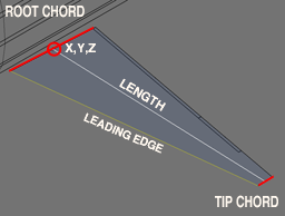
The mid-chord root of the wing serves as the base location of the flight surface. Provide x,y,z coordinates for the base as shown in the picture. This is always the left surface for wing, hstab and mstabs-- the right surface is automatically generated via mirroring. Vstabs are not mirrored, so if such flight surfaces are to be symmetrical, you must provide two separate vstabs where the right-side y coordinate is likely to be the negative of the left-side y.
length
Measure length from the middle of the root chord to the middle of the tip chord. Make certain you are not measuring the leading or trailing edge.
chord
This is the length of the root chord.
taper
Taper is the ratio of the tip chord length to the root chord length and is one of the two attributes (with sweep) that defines the shape of a flight surface. If a wing tip has a chord of 2 meters and the root a chord of 4 meters, then taper is 0.5 (2/4). A simple straight wing where all ribs have the same chord would have a taper of 1, the so-called "Hershey bar" wing. The default taper is 1.
sweep
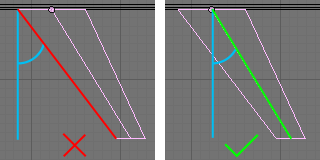
This is the angle of the wing's mid-chord line with respect to the station line (usually the x-axis running front to back through the fuselage). Sweep should not be measured based on the wing's leading edge. A wing with a sweep of 0 has a mid-chord line that is 90 degrees to the station line-- it sticks straight out for the fuselage. A wing with a 45 degree sweep would have the classic delta appearance. A wing with a negative sweep would actually bring the wing tips forward, as is done in some sailplanes and experimental designs. Measure sweep from the wing's origin. Sweep defaults to 0.
The image at right shows the wrong way and then the right way to find sweep. Don't use the leading edge, use the mid-chord line.
dihedral
The angle of the wings with respect to the fuselage, as seen from the front or aft view of the aircraft. A positive dihedral is a rotation of the wing upward, lifting the wing tips. A negative value (also called anhedral), is a rotation of the wing downward, drooping the wing tips. Most aircraft, especially low-wing aircraft, have a positive dihedral. Some like the An-124 and the Harrier have an anhedral. Dihedral is measured from the wing's origin. The default is 0.
Dihedral affects stability along the roll axis by helping to keep the wings level in flight without pilot input. In flight, a roll to one side allows a component of the wing's lift vector to pull the aircraft sideways, causing a sideslip. With a positive dihedral, the sideslip slightly rotates the lowered wing forward, bringing it into a higher angle of attack than the opposing wing. The result tends to bring the aircraft level again. Too much dihedral can make the plane too resistant to roll or cause wallowing dutch roll behavior. An anhedral has the opposite effect and is often used as compensate for roll resistance in aircraft where the center of gravity is lower than the wing. (The B-25 has a curious gull-wing dihedral because the prototype with its continuous dihedral exhibited stability issues, dutch rolls, and couldn't do flat rudder-only turns, a requirement for bomb runs. The cranked-wing configuration solved these issues.)
A simple measurement of the dihedral angle may not give you the desired simulation results. Other design factors contribute to roll stability. Some aircraft have very little dihedral yet are very stable in rolls. Some with extreme anhedrals suggest an unstable aircraft, when in fact the aircraft is very docile. Apparent dihedral angle is only the first step in choosing a value for YASim. You must have a good feel for the design and the behavior of the aircraft to select a good value.
|
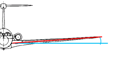
YASim's fixed stabilizer incidence is in some ways an unfortunate design choice. YASim determines stabilizer incidence such that the aircraft will fly level with no elevator input at max cruise speed. But many planes were not optimized for cruise flight. The original Beech Twin models had a low stabilizer angle optimized for low-speed flight, making them a delight on approaches, but cruise performance suffered. After the war when models were being produced primarily for civilian markets, the demand was for better cruise performance, so Beech increased the stabilizer incidence. Pilots used to the old performance often disliked the change, though owners paying for fuel appreciated it. You can observe the difference by looking for the curiously high fuselage-stabilizer fairing on the later Beech 18 models. |
incidence
This is the angle between the fuselage station-line or longitudinal axis, and the wing's chord line. Most wings have some positive incidence (the leading edge is higher than the trailing edge) to improve visibility on approach, shorten takeoff rolls, reduce drag by better aligning the fuselage with the relative wind, etc. If incidence is not known, 2 or 3 degrees is a good guess for general aviation aircraft. Incidence defaults to 0. Incidence affects stall behaivor. See YASim's stall element.
You cannot define the incidence of horizontal stabilizer (hstab) element. YASim sets this for you, it's part of the purpose of the solver. If you try to define an incidence for an hstab element, it will be ignored. You can offset this effect somewhat by applying a non-zero trim control setting in the cruise settings. More on this later.
twist
Most conventional planes have some degree of wing twist that makes the inboard wing stall before the outboard region where the ailerons live. Twist spreads out stall effects over time and helps maintain control during the onset of the stall. Wing twist can be geometric or aerodynamic. A geometric twist is a progressive decrease in incidence from inboard to outboard wing stations-- the wing is literally twisted. This is also called 'washout'. Aerodynamic twist is the difference between the zero-lift angles of the root and the tip airfoils-- the airfoil actually changes shape from root to tip. If not known (and it often isn't given in pilot handbooks or other sources), use -2 or -3 degrees for twist. Twist defaults to 0. For more on twist, see YASim's stall element.
camber
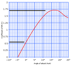
Camber usually refers to the asymmetry between the top and bottom surfaces of an airfoil, but in YASim it is defined as the ratio of the airfoil's lift at 0 degrees angle of attack to the maximum lift at critical alpha. In other words, the percentage of the maximum (stall) CL that occurs at zero degrees angle of attack. More camber means more lift at low alpha values, but also more drag. The figure at right shows a lift curve for an airfoil. Here, the CL value at 0 AoA is 0.55, and is maximum at 1.7 when the critical stall AoA is about 16 degrees. Camber for this airfoil can be estimated by 0.55/1.7 = 0.32. This is a thick, high-lift airfoil that no doubt has a ton of drag. Most will have cambers much less than this.
A camber of 0 represents a symmetrical airfoil, and this is the YASim default. Most general aviation aircraft will have some camber. If you cannot find YASim camber for your airfoil, try values like 0.05 up to 0.1. These work reasonably for old but common airfoils like NACA 23015 etc.
Airfoil CL findings will be higher than those of an actual wing using that airfoil due to the effects of the spanwise pressure gradient. This is the same effect that causes [induced drag]. The spanwise pressure gradient reduces the effective CL by 10-20%. So a good high-aspect wing can expect a true lift coefficient of about 90% of theoretical CL. A low-aspect wing might get 80%. For something in the middle, try using 85% of the theoretical airfoil CL.
Stabilizers are usually thin and symmetrical as they are not usually expected to produce much lift and should have minimum drag. Horizontal stabilizers sometimes have negative camber values, particularly with STOL or heavy-lift cargo aircraft where high-cambered wings with large flaps are designed for maximum lift and have strong negative pitch moments. Canard hstabs usually have high stabilizer loadings and tend to have significant positive camber. Aircraft with all-moving stabilizers will usually have symmetrical airfoils.
induced drag
This takes a little explaining and so I have a separate page dedicated to Induced Drag. Here's the short version: The YASim idrag value defaults to 1. Increasing the value above 1 reduces induced drag. Decreasing the value increases induced drag. This is opposite of what you might expect and what the documentation says. It's likely due to a long-standing bug in the YASim code. I recommend not messing with idrag until you have a good solution and know what you are doing.
effectiveness
This is a scalar applied to the drag derived from the form factor of flight surfaces. In effect it's a modifier for parasitic drag. The attribute is very badly named, and maybe should have been called "pdrag", similar to "idrag". The value defaults to 1. [Note: In my original YASim guide I mistook "effectiveness" with the similarly named "flap effectiveness" control, which is a different beast. The confusion resulted from the unfortunate use of the same name used by a control, the almost non-existent documentation, and my mistake in examining the code base.]
When applied to a wing, increasing this drag factor will generally bring solution drag coefficient and lift ratio numbers closer together while reducing elevator authority. Decreasing it will have the opposite effect. When applied to an hstab, increasing the drag factor increases the spread between drag coefficient and lift ratio numbers (though the effect is slight due to the much smaller surface area typical of stabilizers), and tends to increase elevator authority, radically in the case of canard aircraft, probably because the elevator is ahead of the CG and the increased drag is trying to pull it behind the CG. Decreasing it does the opposite.
When applied to hstabs, "effectiveness" can have a strong effect on elevator authority. This can lead a developer to use it to force solutions where reasonable values for elevator lift failed, when the real problem was poor CG positioning or unbalanced wing moment effects. In reality, a magnified tail surface windvane effect is obscuring more fundamental problems. In my opinion, use of this attribute should be avoided, especially for hstabs, at least until you have a good solution using proper weight and balance numbers.
The Flightgear wiki has a line in "Howto: Understand Console Output" that recommends adding an "effectiveness" attribute when dealing with solutions that fail to converge. This is a terrible idea, like slapping a patch on an already bad repair. Don't do this. If you have to resort to "effectiveness" to get a solution, you're doing something wrong.
Though poorly documented and badly named, "effectiveness" when used right may be interesting, allowing you to change the parasitic drag of flight surfaces. In YASim, this drag is based on the surface area of any given flight surface, which will not account for many factors such as rivet-studded wings, excessive pylons, disruptive engine nacelles, unusually clean surfaces, vortex generators, etc. The "effectiveness" attribute might be useful for increasing the drag of surfaces with lots of struts or wire supports. Using "effectiveness" to modify parasitic drag of a wing or mstab might be helpful for "dirty" aircraft" when you have trouble bringing drag coefficient and lift ratio values closer together. Avoid using it to get better elevator authority.
The Stall Sub-Element
The stall sub-element controls the stall behavior of the flight surface, in other words, what happens at the critical angle of attack. It also affects the lift of the surface. Each surface must have a stall sub-element. A typical stall sub-element looks something like this:
<stall aoa="14" width="8" peak="1.5"/>
Width will default to 2 and peak to 1.5. The peak default is fine-- don't mess with it until you understand what it does. A width of 2 is very narrow for general aviation wings-- I recommend using higher width settings for most general aviation applications. You should always provide an aoa attribute.
Determining values for stall AoA and width is a matter of airfoil study. Optimally, you want to identify the airfoil used and locate a report that plots lift vs. angle of attack (AoA or alpha) for a given airfoil at Reynolds numbers appropriate to your aircraft. This is the same data you'll need to calculate YASim camber as discussed above. (Check the report carefully-- some graphs may be plotting values at low Reynolds numbers for small-scale aircraft. The data will be very different for full-scale aircraft.) Often airfoils used by modern aircraft will be either proprietary or a hybrid, in which case you can either make an educated guess or interpolate from similar known airfoils. Keep in mind that airfoil data is for the airfoil section-- wings using that airfoil won't perform as well due to spanwise pressure gradient effects.
Understanding how YASim's stall element works is important to the creation of a good FDM. I have a separate guide for a more complete discussion on YASim's stall element.
Generally speaking, you want the wing to stall before the horizontal stabilizer in order to maintain elevator response up to the aircraft's stall. For canards this is reversed-- the stabilizer should stall first. Wing loading for a canard stabilizer is higher than that of a conventional stabilizer. For starters, set stabilizer stall AoA a couple of degrees higher than than the wing stall AoA, or a degree or two lower in the case of a canard.
If you have nothing else to go on, try these values for a generic sport aviation configuration:
wing: <stall aoa="14" width="8" peak="1.5"/>
hstab: <stall aoa="16" width="4" peak="1.5"/>
vstab: <stall aoa="16" width="4" peak="1.5"/>
Some guidelines: Most general aviation airfoils will begin to stall in the 14-17 degree range, before considerations for twist or incidence which will lower stall angles. High-lift airfoils might begin to stall as low as 10 degrees or so, but it really depends on the particular airfoil. Delta wing configurations often achieve very high alphas before they stall. As a rule, widths should stay in the 2-12 range, with 2 being a very sharp post-stall lift falloff, and 12 being a fairly gentle falloff. Leave peak at 1.5, or consider reducing peak if you understand peak. Numbers outside of these ranges should be viewed with suspicion unless you are certain of what you are doing. When testing stall characteristics, keep in mind that stall is a function of angle of attack, not airspeed.
|
Lions and tigers and segments, oh my! Control surfaces have an effect on the amount of work YASim must do. A surface with no control element (flaps, slats or spoilers) is a single segment, with all math operating on that lone segment. When you add control elements, the surface begins to be split into two or more segments, and the calculations are replicated for each segment. For example, if you have a wing with a single control element for ailerons starting at 0.5 and ending at 1, the surface would be split into two segments, one spanning 0 to 0.5, and a second spanning 0.5 to 1. If your aileron ended instead at 0.9, then the surface would be split into three segments: 0 to 0.5, 0.5 to 0.9, and 0.9 to 1. If you have flaps, slats, and spoilers, YASim will create many segments, each having the required combined characteristics required for that slice of the surface. So the more surfaces you have, and the more segments each flight surface has, the more work YASim has to do. |
Control Surface Sub-Elements
Now that you know something about flight surfaces, you might be wanting to know how to set up things like ailerons and elevators. These are created by adding control sub-elements to the surface elements. There are three kinds of control sub-elements:
flap[0/1]
slat
spoiler
Control sub-elements have these possible attributes:
start
end
lift
drag
aoa
Let's examine each control element and see how the attributes are used.
Flaps
Each surface may define up to two "flap" elements. YASim uses the name "flap" to denote any movable trailing edge surface, so it could be an elevator, a rudder, an aileron or a true flap. A surface is not required to have any flap elements, but most will have at least one. Wings will usually have one for ailerons and often a second for true flaps. Stabilizers will have one for the elevator or rudder. You cannot define more than two flap elements for a surface. If you need more, you might have to split the surface using mstabs.
A flap element typically looks like this:
<flap0 start="0" end="0.597" lift="1.5" drag="2.5"/>
You must name your flap element either "flap0" or "flap1". You can have two sub-elements if you use both names. You cannot have a flap sub-element called "flap2"; you're allowed only two. Usually "flap0" is used for true flaps, and "flap1" is used for ailerons, but it doesn't matter. The actual assignment is controled by input/output sub-elements, which I'll talk about a little later in this guide.
|
Flap implementation is one of my YASim annoyances. The only values you can tweak are "lift" and "drag". Real flaps allow for an increase of the coefficient of lift. They do so by increasing incidence and changing the camber of that wing segment. Many implementations also extend the wing's chord. One of YASim's strengths is its ability to calculate the effects of a unique wing segment and contribute those effects to the flight surface. YASim could easily have a flap attribute for incidence, camber, and even chord, but instead it provides only a simplified lift attribute with a rather arbitrary moment effect. A great strength of YASim is wasted. |
For a flap sub-element you will have start and end positions indicating where the flap resides along the length of the surface, a lift attribute, and a drag attribute. For start and end positions, start should be nearest the root of the surface, and end should be nearest the tip. The are normalized values, i.e., 0-1. If the flap starts at the very root of the surface, then set start to 0. If it ends at the tip, set start to 1. If a flap starts at 25% of the surface length and ends at 90% of the surface length, set start to 0.25 and end to 0.9.
Lift and drag are more subjective. These are multipliers to lift and drag, so the default values are 1, which leaves lift or drag unchanged with flap deployment. Be careful in your flap lift settings. A high lift value for true flaps has a large effect on the pitching moment of the aircraft and can make it difficult to get good solution results. 1.3 to 1.4 are reasonable values for flap lift. Sometimes you can find references that suggest good starting values. For example, split flap characteristics are often cited as providing a maximum of 35% cL increase and 250-300% drag increase. While this doesn't translate nicely to YASim flap lift values, still you would not go far wrong if you began with lift="1.35" and drag="2.75" for split flaps. Drag for true flaps will often greatly exceed lift.
Aileron lift values will rarely exceed 1.2. Be conservative in your aileron lift settings. Most of mine tend be on the order of 1.15 or so. Elevator lift values are often fairly strong, in the 1.3 to 1.8 range. A discussion of elevator lift value belongs in a section relevant to YASim solutions. Rudder lift values tend to be 1.2 to 1.4. We can't enter moment coefficients for yaw, so all we can do is validate values against known performance in crosswind conditions or side-slipping. For aileron, elevator and rudder drag, I use values slightly less than the lift settings. Fly and test your results.
Slats
<slat start="0" end="1" aoa="3" drag="1.1"/>
In YASim, slats are used to increase the effective stall AoA for that surface. A given surface may have a single slat definition, or none. A slat definition should have start, end, aoa, and drag attribute. Slats cannot have a lift attribute. Slats work by increasing the stall AoA defined in the wing's <stall> element for the surface segment defined by the slat start and end points. For example, if a wing has a stall AoA defined as 14 and a slat with an AoA of 2, then when slats are fully deployed, the surface segment will have an effective stall AoA of 16. If slats where 50% deployed, the stall AoA would be 15. I'll talk about how control surfaces are deployed later in this guide.
Spoilers
<spoiler start="0.078" end="0.554" lift="0.7" drag="2.0"/>
Spoilers in YASim are a generic term for anything that kills lift or adds drag based on a control. So they might be true lift spoilers, or drag-inducing airbrakes, or both. They operate much like flaps, but lift should be a fractional value and is a multiplier to the surface's pre-stall lift. So a lift value of 1 does not effect lift. A value of 0 would mean that at full deflection the spoiler would eliminate all pre-stall lift. You'll likely want to start by setting lift somewhere in a middle range, 0.5 to 0.7 or so, and tune the results with test flights. Note that true spoilers will have both lift and drag effects, while airbrakes will likely have high drag values and leave the left setting at 1. A given surface may have a single spoiler definition or none.
Control-Input Elements
Control inputs are used to map an input property to a surface control. For example, if you want to use the pilot's elevator keys or joystick functions to control a YASim surface used as an elevator, you have to assign an elevator control property to the YASim surface control. Let's look at an example:
<hstab ...>
  ...
  <flap0 start="0" end="1" lift="1.3" drag="1.3"/>
  <control-input control="FLAP0" axis="/controls/flight/elevator"/>
  ...
</hstab>
Here we have flap0 being used as an elevator. The only thing that defines flap0 as an elevator is the mapping of an elevator control-input property to the surface control. The input is called the "axis", and is just a standard Flightgear property of your choice. The flap's lift and drag properties are interpolated based on the control property value. For example, if "/controls/flight/elevator" is 0.5, the lift attribute of this flap would be 1.3 * (1 + 0.5) = 1.15. This is straight-forward and simple example. Let's look at a wing with two control surfaces, flaps and ailerons:
<wing ...>
  ...
  <flap0 start="0" end="0.597" lift="1.5" drag="2.5"/>
  <flap1 start="0.597" end="0.824" lift="1.25" drag="1.2"/>
  <control-input control="FLAP0" axis="/controls/flight/flaps"/>
  <control-input control="FLAP1" axis="/controls/flight/aileron" split="true"/>
  ...
</wing>
Here we've selected flap0 to be the true flap control by creating an association with the property "/controls/flight/flaps". We've mapped flap1 as ailerons by assigning it the property "/controls/flight/aileron".
Any control assumes an input of 0 means no control deflection, an input of 1 is maximum control deflection in the positive direction (assuming normalized inputs, we'll get to that later) and -1 is the maximum negative control deflection. With flaps, as we increase the control input, flap deflection is increased proportionally, in the same direction. We don't use negative values for flaps. But ailerons work opposite each other. An input that deflects one downward generally sends the opposite one upwards. We don't want to mess with dual controls for ailerons, one positive, one negative, so we set the optional attribute "split" to be true. This negates the control input for the right wing on surfaces that are mirrored and simplifies our task.
What if you want to reverse an input before it is applied to the control surface? There are several ways, but the easiest is to use the optional "invert" attribute:
<vstab ...>
  ...
  <flap0 start="0" end="0.829" lift="1.4" drag="1.3"/>
  <control-input control="FLAP0" axis="/controls/flight/rudder" invert="true"/>
  ...
</vstab>
The most common application of "invert" is the rudder control.
I've mentioned the "split" and "invert" attributes. There is another atttribute set that can help you refine control input values without relying on external methods like scripting. This uses the attributes, "src0", "src1", "dst0" and "dst1". Here's an example:
<control-input control="FLAP0" axis="/controls/flight/mycontrol" src0="-1.0" src1="1" dst0="0" dst1="0.5"/>
In this case, we're taking the possible input range of -1 to 1 and interpolating it to an output range of 0 to 0.5. In other words, if the source property value is -1, the YASim control surface will see 0. If the property is 1, the control surface will see 0.5. These attributes are especially handy if you need to normalize input properties.
Control inputs can also be mixed. You can assign different properties or axes to the same input control by defining two or more controls on the same surface control element. The results are added before being applied to the input control. I've never done this, but I know it's possible. If your inputs are not already well clamped to the desired ranges, you'll probably want to use src and dst attributes to limit the mixed inputs.
There's one special case where you will nearly always use a mixed input: assigning a controls for trimming the elevator:
<hstab ...>
  ..
  <flap0 start="0" end="1" lift="1.3" drag="1.3"/>
  <control-input control="FLAP0" axis="/controls/flight/elevator"/>
  <control-input control="FLAP0" axis="/controls/flight/elevator-trim"/>
  ..
</hstab>
For an hstab, always provide a control-input sub-element for both primary elevator control and elevator trim control. Both inputs are critical for YASim to solve for approach elevator and tail incidence. You must provide both axes on hstabs or YASim will freak and not give you a solution. Usually these controls are mapped to the same elevator control surface, but they could be different control surfaces. Don't be too literal here-- a trim control may physically operate a trim tab, but its function is to trim the main control surface.
We now have an idea how flap control inputs work. YASim offers several other kinds of controls in addtion to flaps:
flap[0/1]
slat
spoiler
flap[0/1]effectiveness
incidence (inoperative)
Let's look at each one and see what it does.
flap[0/1]
As we've seen, the flap control is used for ailerons and true flaps, controlling the deflection of a flap surface. These inputs are clamped to the range of -1:1. In practice you'd use the full range for ailerons, but for true flaps you'd use a range of 0:1.
slat
This is the control input used to map a control property to a slat extension of a wing. Unlike flaps, you are allowed only one slat. It works much like the flap controls. Example:
<control-input control="SLAT" axis="/surface-positions/slat-pos-norm"/>
spoiler
The spoiler extension for a wing. Example:
<control-input control="SPOILER" axis="/controls/flight/spoilers"/>
Unfortunately you are allowed only one spoiler for a surface, which can be a problem for some aircraft that feature multiple spoiler or airbrake devices that are not necessarily deployed according to the same rules. This is common with airliners. There are two things you can do: split the surface into multiple surfaces using <mstabs>, or treat multiple spoilers as a single FDM unit, and use custom Nasal scripting to interpolate the spoiler's deployment based on the status of each "virtual" spoiler. For example, if two virtual spoilers are used and only one is deployed, a controller would deploy the single FDM spoiler to 50%.
flap[0/1]effectiveness
These controls allow a dynamic change to the 'lift' attribute of the specified flap.
<control-input control="FLAP0EFFECTIVENESS" axis="/controls/flight/blownflaps"/>
It is a simple multiplier for the "lift" attribute of a flap. If you had a flap with a lift attribute of 1.3 and a control property having a value of 0.5 and an effectiveness property of 1.25, the result would be 1.3 * (1 + 0.5) * 1.25 = 1.1875.
Don't confuse this with the surface "effectiveness" attribute, a different creature entirely. With the flap effectiveness control and some creative scripting you can simulate blown flaps, or you can use the control to eliminate lift over part of the flap deployment range (maybe; see my final note), which is a step toward simulating Fowler flaps which offer increased lift and minimal drag in the early part of the extension range, but the latter part is mostly drag. These controls are available for both possible surface flaps: "FLAP0EFFECTIVENESS" and "FLAP1EFFECTIVENESS". They do not affect flap drag, and surprisingly there is no flap drag equivalent. Note: the allowed values are supposed to be clamped to a range of O:10, but the code base indicates an actual range of 1:10. This suggests it may not be possible to reduce flap lift, which in my opinion severely devalues this control.
incidence
This control was evidently intended to allow dynamic changes to the incidence angle of a wing, but currently it is inoperative. The control is parsed but not mapped to anything in the YASim code. This is odd since the nature of YASim would make an incidence control very easy to implement. As things are now, you cannot dynamically alter wing incidence in YASim.
The Control-Speed Element
For general aviation, most surfaces respond nearly instantaneously to control inputs. Ailerons are directly linked to a stick or yoke and respond as you move your control. But surfaces like flaps and airbrakes are usually activated by means of electric motors or hydraulics and take a while to extend or retract. YASim gives you an easy means to do this using the control-speed sub element.
<wing ...>
  ...
  <flap0 start="0" end="0.597" lift="1.5" drag="2.5"/>
  ...
  <control-speed control="FLAP0" transition-time="10"/>
  ...
</wing>
Here we've assigned a 10 second interval for flaps to move from from the fully retracted position to the fully deployed position. Any transitions in between will have interpolated time requirements, so a move from retracted to half-deployed requires 5 seconds.
Transition times can be defined for any control surface but in practice you'll use them only for flaps, slats and spoilers.
The YASim document tells us that this sub-element is semi-deprecated, but this is nonsense. For most surfaces requiring transition times, this function is good enough and is much more efficient than Nasal solutions. It should be your first choice. But it is a simple, linear transistion. If you have a more complex or non-linear situation, don't hesitate to pre-process control inputs using Nasal scripting rather than use the control-speed sub-element.
Control-Output Elements
Control outputs are the reverse of inputs. They allow you to export YASim's internal control position values as Flightgear properties.
<hstab ...>
  ...
  <control-output control="FLAP0" prop="/surface-positions/elevator-pos-norm"/>
  ...
</hstab>
Here we're exporting YASim's value for the current position of an elevator to the property "/surface-positions/elevator-pos-norm".
This has several uses, the primary one being animations. While inputs issue control signals to YASim, but they are not necessarily indicative of where a surface actually is. An aileron response might be virtually instantaneous, but flaps take a while to deploy-- it might be many seconds before flaps have reached the position indicated by the input control.
Since YASim can split control inputs into two inverted values for the left and right side surfaces, it's sometimes useful to extract those different side values and set them on separate properties. The most common use of this is for aileron animations:
<wing ...>
  ...
  <control-input control="FLAP1" axis="/controls/flight/aileron" split="true"/>
  ...
  <control-output control="FLAP1" side="left" prop="/surface-positions/left-aileron-pos-norm"/>
  <control-output control="FLAP1" side="right" prop="/surface-positions/right-aileron-pos-norm"/>
  ...
</wing>
You can constrain the range of these output values using the optional "min" and "max" attributes. If you wanted to constrain an output to a maximum of 0.5, you could set max="0.5" and the output property would be clamped to a maximum of 0.5. I've never had reason to do this, but the options are there.
Thoughts on creating flight surfaces
Keep it simple. Don't define unnecesary surfaces and keep the geometry basic. If a wing can be done reasonably with a single surface, then express it as a <wing>, not a <wing> and <mstab>. Don't add vstabs for every pylon or extra fin seen on the plane-- quite often the intent of these surfaces is not obvious or beyond the simulation capabilities of YASim. Many of the small surfaces commonly seen on T-tailed aircraft are meant to reduce deep-stall effects, and YASim doesn't simulate deep-stall conditions. Some designers add vstabs to represent winglets on the wingtips of airliners, but the point of such things is to minimize induced drag-- their other aerodynamic and weight effects are very small and ususally not worth creating a surface. Instead, tweak the idrag value for the main wing. The simpler your FDM, the more likely it is that you will get good results and the easier it will be to adjust the portions that matter most.
When defining flap positions, don't try to be ultra precise. If ailerons begin at mid wing and extend 98% of the way to the tip, then don't set start="0.5" end="0.98", set start="0.5" end="1". That tiny .02 sliver forces YASim to create an extra surface segment for dubious benefits. Chances are you are approximating positions anyway, so use values that create the least number of surface segments and allow YASim to operate efficiently.
YASim doesn't give us the capability of entering wind tunnel numbers to get our results, that's not its method, but this doesn't mean you can't get reasonably realistic flights. It does mean you have to research your aircraft and do very many flight tests to fine-tune individual attributes. The attribute values are not what you care about. The flight behavior is what you care about. Pilot reports and handbooks are your friend here. If you have no hands-on experience with the aircraft yourself (and even if you do!), study as many reports from others as you can. YASim is not an easy out-of-the-box solution. If you want to approximate reasonably realistic behavior, you will have to work at it. There is no magic solution.
Document your FDM settings in the FDM itself. Many settings are not intuitive especially to inexperienced designers. You may have spent a great deal of time and effort researching a behavior and tweaking an attribute for flight results, but if you don't document your rationale no one will know why those values were chosen, and it's very possible some enthusiastic but inexperienced follow-on developer may change your values without understanding them. Lack of proper documentation is probably the greatest flaw of YASim itself. Don't make the same mistake in your FDM.